Wheel odometry statistics (ws_stats)
Objectives
Evaluate the correlation between the Fusion-based estimated velocity and the wheelspeed input in every dimension and as vector magnitude (speed).
Assess the quality of the scale factor estimation and its convergence time.
Analyze the performance of the stationary detector.
Evaluate if the wheelspeed input will improve the positioning performance of the Vision-RTK2.
Explanation
The wheel odometry statistics file allows the user to evaluate the performance of the velocity measurements inputted to the Vision-RTK2 from an auxiliary sensor (e.g., wheel encoder) or a motion model (e.g., kinematic model). This file compares the sensor's estimated velocity based on the Fusion engine and the input velocity from each configured sensor (e.g., center, front-left, front-right, rear-left, rear-right). For reference, the estimated scale factor (i.e., the estimated unit scale of the input measurements) is displayed at the top of the file in brackets.
The file compares the estimated speed (vector magnitude) and evaluates the velocity input at any individual dimension. The user can then assess whether the velocity input correlates highly with the Fusion estimate in every dimension, providing a comprehensive view of the system's performance.
In addition, the file presents the estimated velocity from each GNSS receiver for comparison. This information allows for discarding possible failures in the Fusion engine and comparing directly with each receiver's raw GNSS measurements.
Moreover, the file displays the wheel speed convergence and stationary flags, allowing the user to determine how long it took for the wheel odometry values to converge and analyze the performance of the stationary detection block on the platform using the selected operation mode (e.g., car, generic, lawnmower). Please get in touch with support@fixposition.com for further guidance on the matter.
Lastly, the file presents the estimated scale factor of each sensor over time. This plot allows the user to determine if there is an issue with the input stream. For example, if the measurements present high delays or noise, the scale factor will not converge, and the Fusion engine will not employ these measurements.
For more information on streaming wheelspeed measurements to the Vision-RTK 2, please refer to Section 5.8 of the Integration Manual.
Expected results
The input velocity of each auxiliary sensor must highly correlate with the estimated velocity of the Fusion engine. The file will compensate for lever arm effects as long as the input extrinsics are correct.
The velocity estimated by the GNSS receivers will highly correlate with the Fusion-estimated velocity when the device is under RTK-fixed or RTK-float conditions. Differences between these outputs are expected during GNSS outages.
When the vehicle speed is zero, the stationary detector must be activated. Otherwise, small velocities are likely being sent to the Vision-RTK2, preventing it from accurately detecting the stationary status.
Once the scale factor converges, the estimated value should remain stable throughout the recording. If significant fluctuations are observed, it is likely that the values are not converging in all axes or that the auxiliary sensor was configured as 'unsigned' when the measurements were 'signed'.
The file displays all axes of the velocity vector regardless of whether these are enabled on the input sensor. Make sure to enable all desired axes on the Web Interface.
Examples
Below is an example of the wheel odometry performance on a slow-moving vehicle with four auxiliary sensors (i.e., front-left, front-right, rear-left, and rear-right encoders). Fig. 1 shows a high correlation between every sensor's input velocity measurements and the VRTK2's estimated velocity. In addition, the wheelspeed factor for all sensors is virtually the same, indicating that the measurements are correct.
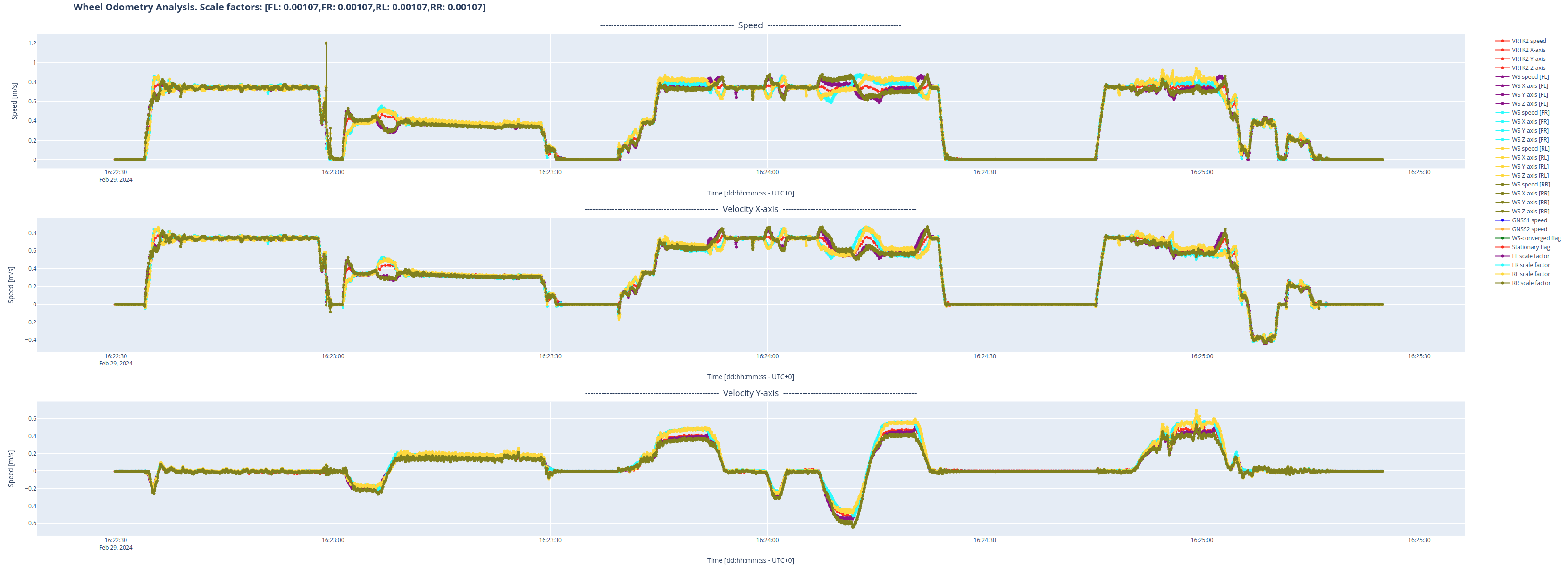
Fig. 1: Comparison between each sensor's input and the estimated velocity using the Fusion engine.
Furthermore, as a second reference, Fig. 2 shows that the velocity input highly correlates with the velocity reported by the GNSS receivers. In addition, when the velocity is zero, the stationary detector accurately detects the vehicle is stationary.
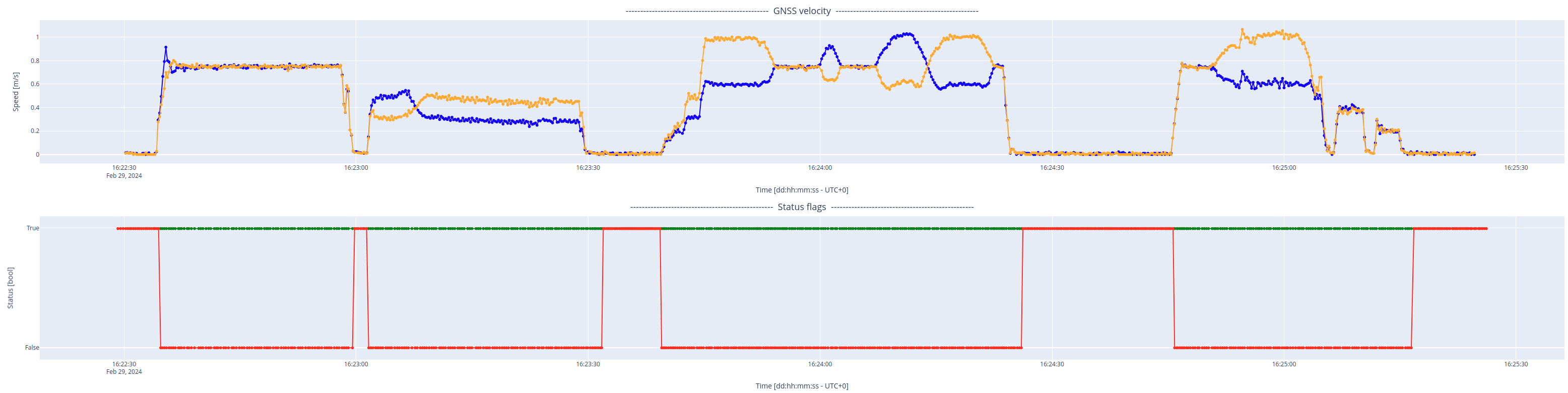
Fig. 2: Velocity estimation of each GNSS receiver and status flags.
Moreover, as presented in Fig. 3, the user can observe that the estimated scale factor has been stable throughout the recording, indicating that the Fusion engine fully uses the input velocities.
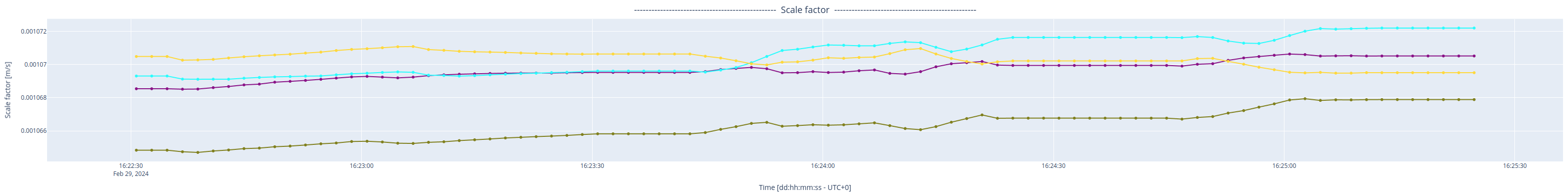
Fig. 3: Scale factor of each input sensor.
Therefore, the user can conclude that the input values are healthy and that the Fusion engine can adequately employ them to increase performance in prolonged GNSS outages.
The estimated velocity of the Vision-RTK2 is not in the same reference frame as the input of each auxiliary sensor. The sensor extrinsics are employed to generate an accurate rigid-body model to correct this. If the extrinsics are erroneous, the plots might present some slight deviations.
Example HTML:
If the auxiliary sensor can input both positive and negative values, it is crucial to configure the sensor as 'signed' on the Web Interface. Otherwise, as shown in Fig. 4, the Vision-RTK2 will not be able to assess the scale factor's sign accurately, and the Fusion engine will not employ the measurements.
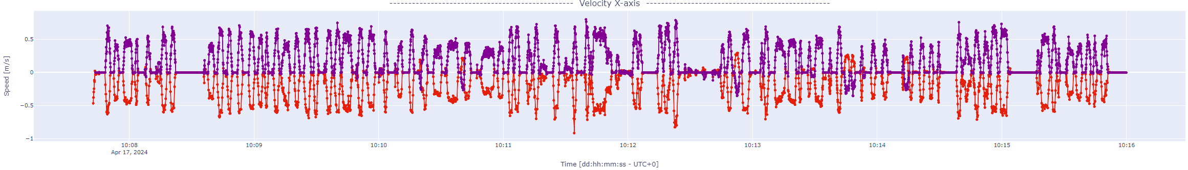
Fig. 4: Erroneous sign of the scale factor due to misconfiguration of the sensor.
Lastly, as shown in Fig. 5, if the input extrinsics are incorrect, the user might observe some strange behaviors on the X and Y axes, where the input stream seems to highly correlate with the Fusion-estimated velocity when the sensor is moving on a straight line, but differing when the vehicle performs a rotation.
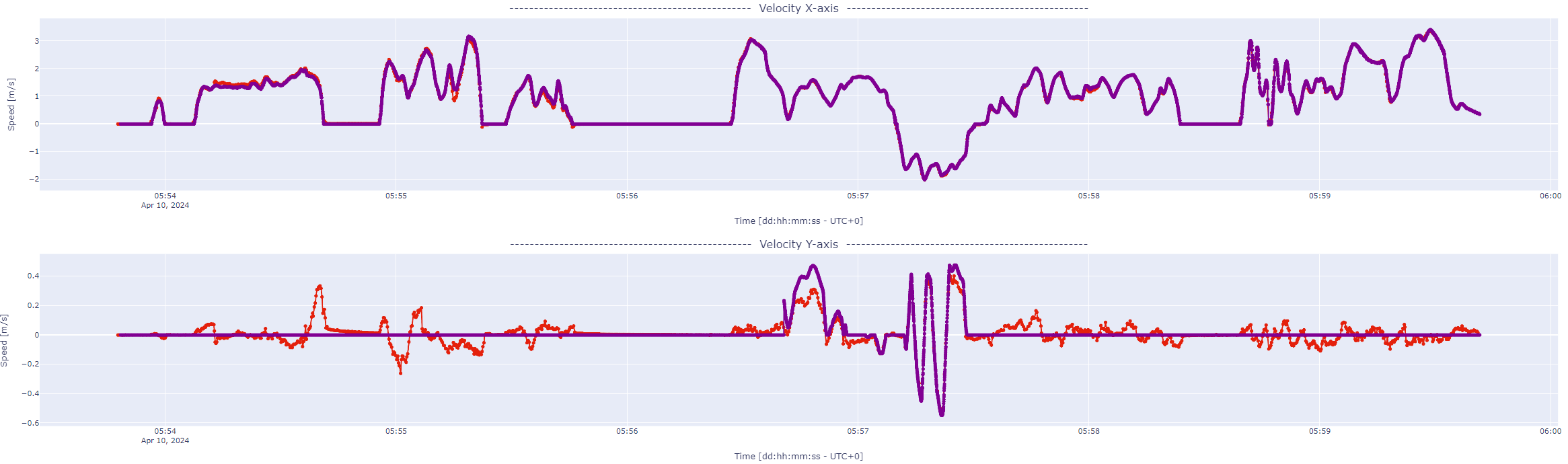
Fig. 5: Strange behavior on the X and Y axes due to incorrect input extrinsics.
Further analysis
Make a recording with the vehicle moving and turning for about 5 minutes under good RTK fixed.
When using CAN for the wheelspeed input, enable the 'Record raw CAN' option to debug the CAN messages received in the port. Please disable this option after the recording, as it consumes significant CPU resources.