Fixposition CAN frame
The Fixposition CAN frame is not a CANSTR message. See Section 5.5.3 of the Integration Manual for more information on their differences.
A generic speed input CAN message as specified in the Excel or PDF file “fixposition-can-frame-new” (see bottom of this page) can be used similarly to the generic I/O port wheelspeed input. It can support one, two, or four wheels (or differential wheelspeed) sensors.
This CAN frame should be sent by the user at regular intervals. The input rate must be at most 50 Hz. The latency (from taking the measurement on the wheel to broadcasting it on the CAN bus) must be as low as possible. Increased, and in particular, irregular, latency degrades the VRTK performance.
To enable processing of the messages received on the CAN bus one or more sensors have to be configured.
This document defines a CAN (Controller Area Network) frame to provide wheelspeed measurement to the Vision-RTK 2. CAN is a robust vehicle bus standard designed to allow microcontrollers and devices to communicate with each other in applications without a host computer. Note that each parameter and bit is crucial for ensuring the correct operation of the CAN network and proper interpretation of the data by all devices on the network.
It is important to consider these parameters mentioned in the .pdf below:
In the following, the parameters are described in detail.
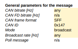
General Parameters for the Message:
CAN Bitrate: This is the speed at which the data is transmitted over the CAN network. We are flexible with this parameter as long as the bandwidth allows sending the wheelspeed measurements at a reasonable rate. Make sure this setting aligns with your bitrate
CAN FD Bitrate: CAN FD refers to CAN with Flexible Data-rate, an extension to the original protocol that enables faster data transmission. The Fixposition CAN frame does not support this mode.
CAN Frame Format: Specifies the format of the CAN frame. "SFF" stands for Standard Frame Format, meaning it uses a standard 11-bit identifier.
CAN ID: This is the identifier for the CAN message. The Vision-RTK 2 natively recognizes the Classic CAN message for wheelspeed input with ID: 0x147 for header information and 0x148 for data input when using the adequately configured payload.
Mode: Indicates that the message is a broadcast message, which is sent to all nodes on the network.
Broadcast Rate: The rate at which this message is broadcast, which is 50 Hz.
From 2.102.2 onward, the CAN ID 0x146 is deprecated and thus not supported anymore
CAN Frame Definition:
This section specifies how the CAN frame's payload is constructed. Some examples are presented here for reference, such as Intel bit numbering and Motorola bit numbering (also known as Intel and Motorola endianness). Endianness refers to the order of the bytes.
It breaks down each byte of data and the bit positions within each byte.
The FR, FL, RR, and RL data readings (abbreviations for Front Right, Front Left, Rear Right, and Rear Left) refer to sensor readings from the respective corners of a vehicle. RC refers to a velocity in the same rigid body as the Vision-RTK 2.
The values are represented as signed 16-bit integers, and the data resolution (0.01m/s, for instance) and validity (0xffff = invalid) are defined.
Example:
It provides an example of how values are represented in the payload.
FR = 1.234 m/s translates to a hex value 0x04d2 in the payload.
It also shows how an invalid or not applicable value is represented with 0xffff.
CAN Frame Payload:
The payload representation shows how the data would be encoded in binary within the frame.
This section illustrates the actual bits that would be set in the message payload according to the definitions above.
Currently, only time of arrival (ToA) timestamping is supported.
Excel file:
fixposition-can-frame_new.xlsx
PDF file: