Using RS-232
Background
The Vision-RTK 2 features two UART I/O interfaces. They use TTL level signals (3.3 V). These logic-level interfaces are not RS-232. RS-232 uses different voltage levels and signaling. In order to connect Vision-RTK 2’s one of the UART1/UART2 to an RS-232 serial port a conversion of the signals is required. For this, one can for example use a MAX232 series chip. However, many breakout boards are available from the usual sources and the circuit is also simple to build from scratch. For more information, see the links at the end of this page.
Fixposition RS-232 cable
Fixposition can supply a kit to connect the Vision-RTK 2 sensor to RS-232 equipment. Kindly contact us at accounting@fixposition.com to place your order and for more information on the lead time and pricing.
Available cables
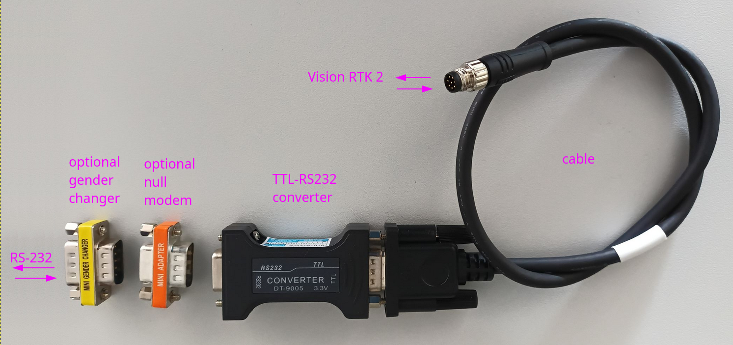
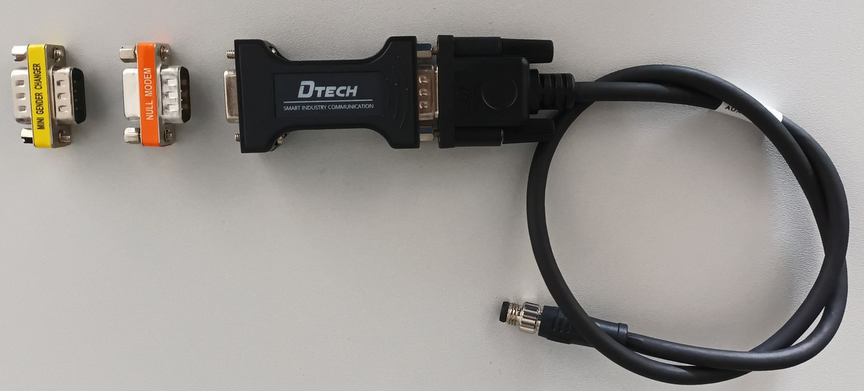
Two kits are available. They consist of:
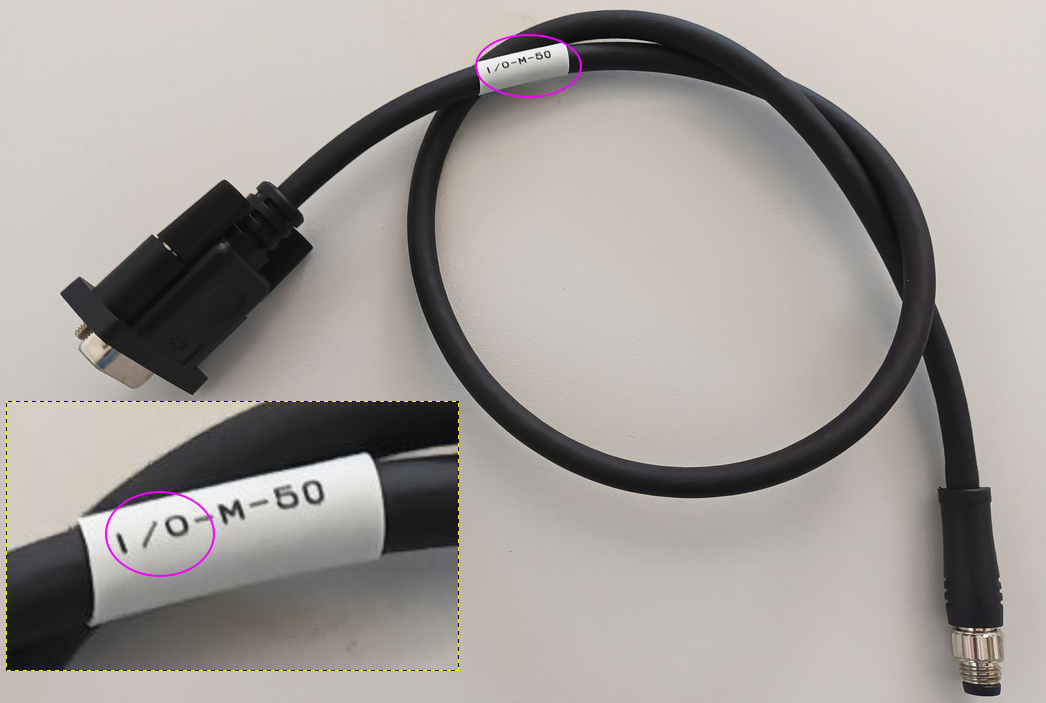
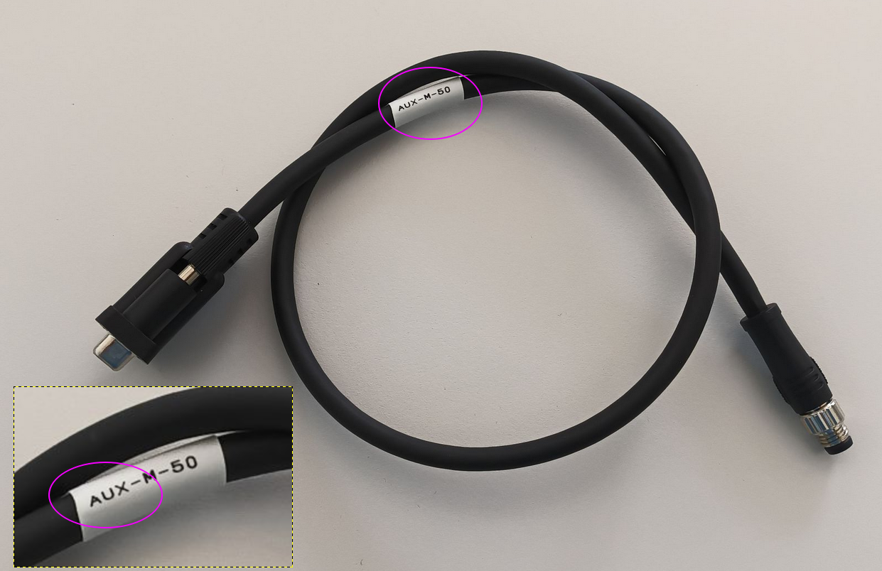
A cable from either the I/O connector (UART1) or the AUX connector (UART2)
Note that even though the cables have the same connectors at either end, the wiring is different. That is, as the I/O cable only works for the I/O connector (UART1) and the AUX cable only works for the AUX connector (Section 3.2.3 and 3.2.4 in the Integration Manual)
The length of the cable is deliberately short so that the TTL level signals do not distort or attenuate too much, which can easily happen and is more likely the longer the cable is.
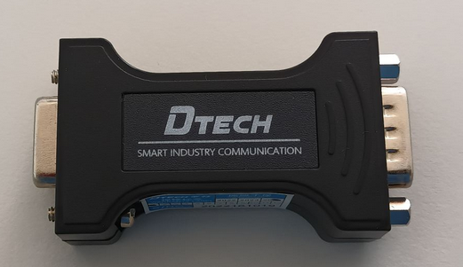
A converter to match the UART TTL signal levels on one side with the RS-232 signal levels on the other side. The adapter is bi-directional and works for outputting from the Vision-RKT 2 as well as for inputting to the Vision-RTK2.
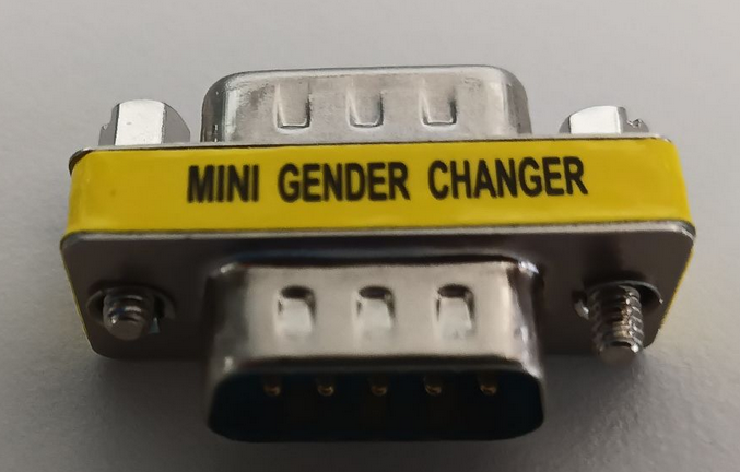
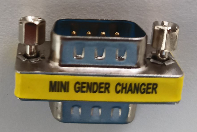
A DE-9 gender changer that can optionally be used to change the gender on the RS-232 side
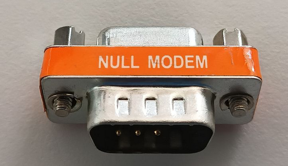
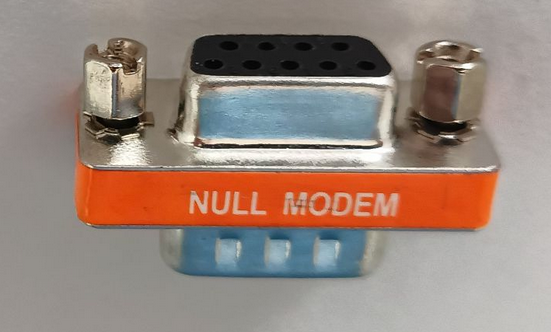
A DE-9 null-modem adapter that can be used optionally to swap the RX and TX lines on the RS-232 side.
Kit 1: UART1 (I/O connector) ↔︎ RS-232 | Kit 2: UART2 (AUX connector) ↔︎ RS-232 |
|---|---|
Cable for I/O connector (UART1) | Cable for AUX connector (UART2) |
 |  |
Adapter UART TTL signals ↔︎ RS-232 signals | |
 |  |
 |  |
Null-modem adapter (swaps RX and TX signals) | |
 |  |
Gender changer | |
 |  |
Usage
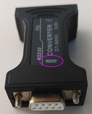
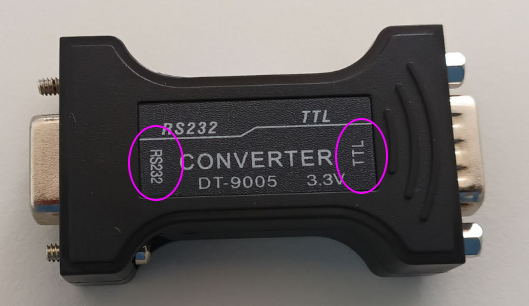
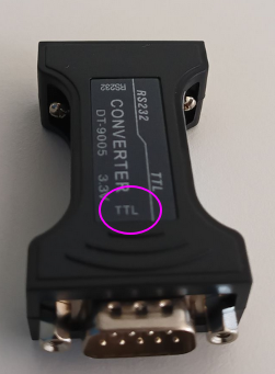
Connect the TTL-RS232 converter to the cable. The converter’s side marked with “TTL” should connect to the DE-9 end of the cable as shown in the image.
Optionally, and depending on your RS-232 equipment, add the gender changer and/or the null modem adapter(s).
Connect the cable to the Vision-RTK 2
Depending on which cable you have, connect either to the I/O port or the AUX port.
Connect the RS-232 end of the converter (or the optional adapter(s) from step 2. above) to your RS-232 equipment.
Make sure that the baudrate is set to the same value (e.g. 115’200) on both the Vision-RTK 2 UART port and your RS-232 equipment.
Communication between your RS-232 equipment and the Vision-RTK 2 should now work