Nav2 implementation
Introduction
Nav2 is the official navigation framework for ROS2, designed to enable autonomous navigation for mobile robots in both simulated and real-world environments. It provides a flexible, modular, and extensible architecture for controlling a robot's movement from one point to another while avoiding obstacles, mapping the environment, and managing localization.
Key Features:
Path planning: Global and local planners for efficient route generation.
Localization: Integrates with SLAM or external localization sources (e.g., AMCL).
Obstacle avoidance: Uses costmaps and sensors (e.g., LIDAR, RGB-D) to navigate safely.
Behavior trees: For extensible and customizable decision-making workflows.
Lifecycle management: Nodes can be started, paused, or reset in a deterministic way.
Simulation support: Fully compatible with Gazebo, RViz, and other ROS2 tools.
Nav2 is designed to support a wide range of robot platforms, from simple differential-drive robots to complex, multi-sensor autonomous systems. When integrating custom hardware or sensors, such as the Vision-RTK2, Nav2 can interface through standard ROS2 topics, services, and plugins, ensuring seamless interaction with its navigation stack.
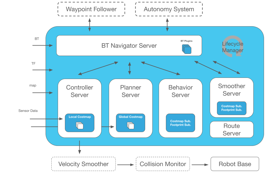
This framework allows the robot not only to move from Point A to Point B, but have intermediary poses, and represent other types of tasks like object following, complete coverage navigation, and more. Nav2 uses behavior trees to create customized and intelligent navigation behavior via orchestrating many independent modular task servers (e.g., compute a path, control effort, behavior, or any other navigation related task). The diagram below will give you a good first-look at the structure of Nav2. For more information, please refer to https://docs.nav2.org/index.html.
There are two ways of using the Vision-RTK2 with Nav2:
(Recommended) The Vision-RTK2 as the only localization sensor on the platform. This method skips the EKF/UKF blocks that fuse multiple data sources and the driver directly generates the TF tree. Please refer to Method 1: Vision-RTK2 as the only localization sensor.
(Work in progress) Fuse the Vision-RTK2 measurements with other sensors (e.g., LiDAR) using the EKF/UKF blocks, but assuming that the Vision-RTK2 is the most accurate one (i.e., non-differential). Please refer to Method 2: Vision-RTK2 as the main localization sensor.